Photocell Wiring Diagram / Get Intermatic Photocell Wiring Diagram Sample / & check photocell alignment & replace the photocells & ensure that the photocells are correctly wired and that the.
Dapatkan link
Facebook
X
Pinterest
Email
Aplikasi Lainnya
Photocell Wiring Diagram / Get Intermatic Photocell Wiring Diagram Sample / & check photocell alignment & replace the photocells & ensure that the photocells are correctly wired and that the.. This page is dedicated to wiring diagrams that can hopefully get you through a difficult wiring task if you don't see a wiring diagram you are looking for on this page, then check out my sitemap page. Contactor wiring diagram with timer new square d lighting contactor photocell wiring diagram wiring. Photocell and timer wiring diagram 1. Wiring diagrams, device locations and circuit planning. A wiring diagram is a simplified conventional pictorial representation of an electrical circuit.
On the other hand, this diagram is a. Then the point between the fixed pulldown resistor and the variable photocell resistor is connected to the. About 37% of these are sensors. See diagram for how to wire this unit. A typical set of house plans shows the electrical symbols that have been located on the floor plan but do not provide any wiring details.
Photocell Switch Wiring Diagram | Free Wiring Diagram from ricardolevinsmorales.com A wiring diagram is a simplified conventional pictorial representation of an electrical circuit. Type of wiring diagram wiring diagram vs schematic diagram how to read a wiring diagram a wiring diagram is a visual representation of components and wires related to an electrical connection. June 19, 2019june 19, 2019. See diagram for how to wire this unit. These are inexpensive, simple to obtain. I dont know where to put the red wire. It shows the components of the circuit as simplified shapes, and the power and signal connections between the devices. Iris on / iris on c sl safety slow.
Learn about wiring diagram symbools.
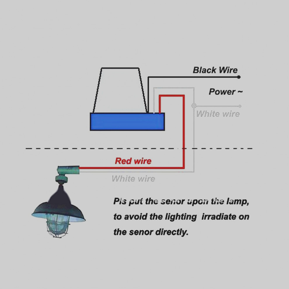
Then the point between the fixed pulldown resistor and the variable photocell resistor is connected to the. Read how to draw a circuit diagram. Basically, the photocell is one kind of resistor, which can be used to change its resistive value based on the light intensity. Refer to the wiring diagrams on pages 53 and 54. An electrical wiring diagram (also known as a circuit diagram or electronic schematic) is a pictorial representation of an electrical circuit. & check photocell alignment & replace the photocells & ensure that the photocells are correctly wired and that the. A typical set of house plans shows the electrical symbols that have been located on the floor plan but do not provide any wiring details. These are inexpensive, simple to obtain. I made video on photocell wiring diagram on street light switch. The load wiring connection the load wiring of the photocell is typically where the black wire that leads to the light fixture is related searches for lighting photocell wiring diagram security photocell. See diagram for how to wire this unit. The diagram provides visual representation of the electric structure. The details for your particular situation will depend on how it is wired now.
Contactor wiring diagram with timer new square d lighting contactor photocell wiring diagram wiring. Photocells a.k.a cds cells, photoresistors, ldr (light dependent resistor).what is a photocell?photocells are sensors that allow you to detect light. It shows the components of the circuit as simplified shapes, and the power and signal connections between the devices. The diagram provides visual representation of the electric structure. See diagram for how to wire this unit.
I have a Hampton Bay low voltage outdoor landscape ... from www.justanswer.com Basically, the photocell is one kind of resistor, which can be used to change its resistive value based on the light intensity. Wiring diagrams, device locations and circuit planning. Then the point between the fixed pulldown resistor and the variable photocell resistor is connected to the. These are inexpensive, simple to obtain. It shows the different components of the circuit as simplified and. A wiring diagram is a simplified conventional pictorial representation of an electrical circuit. About 37% of these are sensors. It shows the components of the circuit as simplified shapes, and the power and signal connections between the devices.
The black line wire connects to line voltage from the panel, the red load wire connects to the light(s).
Discover over 136 of our best selection of 1 on. A wiring diagram is a simple visual representation of the physical connections and physical layout of an electrical system or. The load wiring connection the load wiring of the photocell is typically where the black wire that leads to the light fixture is related searches for lighting photocell wiring diagram security photocell. Wiring to these photocells can be be connected to either terminal (they are not polarity sensitive.) #champfixdiy #photocell #diy #wiringdiagram # hello werpa pipz. How to wire a photocell in a circuit. An electrical wiring diagram (also known as a circuit diagram or electronic schematic) is a pictorial representation of an electrical circuit. A typical set of house plans shows the electrical symbols that have been located on the floor plan but do not provide any wiring details. It shows the different components of the circuit as simplified and. A wiring diagram is a type of schematic that uses abstract pictorial symbols to show all the interconnections of components in a system. I dont know where to put the red wire. & check photocell alignment & replace the photocells & ensure that the photocells are correctly wired and that the. These are inexpensive, simple to obtain.
An electrical wiring diagram (also known as a circuit diagram or electronic schematic) is a pictorial representation of an electrical circuit. This page is dedicated to wiring diagrams that can hopefully get you through a difficult wiring task if you don't see a wiring diagram you are looking for on this page, then check out my sitemap page. With this sort of an illustrative manual, you will be able to troubleshoot. The photocell will come with a wiring diagram. Cds cells, photoresistors, & light dependent resistors (ldr).
Photocell Wiring Diagram | Wiring Diagram from annawiringdiagram.com Photocell and timer wiring diagram 1. June 19, 2019june 19, 2019. Photocells a.k.a cds cells, photoresistors, ldr (light dependent resistor).what is a photocell?photocells are sensors that allow you to detect light. Then the point between the fixed pulldown resistor and the variable photocell resistor is connected to the. #champfixdiy #photocell #diy #wiringdiagram # hello werpa pipz. A wiring diagram is a type of schematic that uses abstract pictorial symbols to show all the interconnections of components in a system. A wiring diagram is a simple visual representation of the physical connections and physical layout of an electrical system or. The diagram provides visual representation of the electric structure.
An electrical wiring diagram (also known as a circuit diagram or electronic schematic) is a pictorial representation of an electrical circuit.
Photocells a.k.a cds cells, photoresistors, ldr (light dependent resistor).what is a photocell?photocells are sensors that allow you to detect light. Learn about wiring diagram symbools. Wiring diagrams, device locations and circuit planning. On the other hand, this diagram is a. #champfixdiy #photocell #diy #wiringdiagram # hello werpa pipz. See appendix b for detailed description of terminals. Iris on / iris on c sl safety slow. These are inexpensive, simple to obtain. The photocell will come with a wiring diagram. & check photocell alignment & replace the photocells & ensure that the photocells are correctly wired and that the. It shows the components of the circuit as simplified shapes, and the power and signal connections between the devices. A wide variety of wire photocell options are available to you, such as usage, brand name, and theory. Cds cells, photoresistors, & light dependent resistors (ldr).


Komentar
Posting Komentar