Wiring Diagram For Multiple Outlets / Diagram Theatre Light Circuit Diagram Full Version Hd Quality Circuit Diagram Glassdiagrams Adimstore It : The diagram will show how a standard switched duplex receptacle is wired.
Dapatkan link
Facebook
X
Pinterest
Email
Aplikasi Lainnya
Wiring Diagram For Multiple Outlets / Diagram Theatre Light Circuit Diagram Full Version Hd Quality Circuit Diagram Glassdiagrams Adimstore It : The diagram will show how a standard switched duplex receptacle is wired.. What is electrical wiring diagram: Also in this platform, the products which they sell here are tested before in hand to know whether they. Duplex receptacle outlets are made for feed through of the power from one receptacle to the next. An electrical circuit diagram is a graphic representation of special characters and pictograms that are connected in parallel or in as a rule, such numbers are necessarily possessed by relays having multiple contact points. On the other hand, this diagram is a simplified version of the structure.
Click on image for larger. A wiring diagram is a comprehensive diagram of each electrical circuit system showing all the connectors, wiring, terminal boards, signal connections (buses) between the devices and electrical or electronic components of the circuit. Wiring multiple outlets in a series. Multi outlet ceiling rose wiring diagram, multiple electrical outlet wiring diagram, multiple gfci outlet wiring diagram,. Any break or malfunction in one outlet will cause all the other.
Diagrams For Wiring Multiple Receptacles Schematics Cord Plug Wiring Diagrams 50cc Light Switch Fordwire Warmi Fr from 101warren.com The electrical calc elite is designed to solve many of. Find out which kinds of diagrams serve which purpose before you try to use them. Wiring diagram a wiring diagram shows, as closely as possible, the actual location of all component parts of the device. I'm wiring the new workshop and want to use 3 way switches to control four outlets running across the ceiling for plug in lights. As shown in the fig, the switch is firstly installed in the wiring the hot wire from switch feeds all the other parallel connected outlets hence, the outlet on/off operation. To wire multiple outlets, follow the circuit diagrams posted in this article. Here is a standard wiring symbol here is a standard wiring symbol legend showing a detailed documentation of common symbols that are used in wiring diagrams, home wiring plans. Single pole switch to an outlet.
Not all wiring diagrams are the same.
The open terminals (marked by an open circle) and arrows represent connections made by the user. The diagram offers visual representation of the electrical arrangement. Also in this platform, the products which they sell here are tested before in hand to know whether they. Multiple receptacle outlets can be connected with lighting outlets as depicted in the above light switch wiring diagram. As shown in the fig, the switch is firstly installed in the wiring the hot wire from switch feeds all the other parallel connected outlets hence, the outlet on/off operation. Click the icons below to get our nec ® compliant electrical calc elite or electric toolkit, available for android and ios. Detailed instructions for wiring an outlet so that half of it can be turned on via a wall switch. Find out which kinds of diagrams serve which purpose before you try to use them. Use wiring diagrams to assist in building or manufacturing the circuit or electronic device. Confused about wiring the electrical system in your van build? This is why a good diagram is important for wiring your home accurately and according to electrical codes. To wire multiple outlets, follow the circuit diagrams posted in this article. How to wire a switched outlet with a single pole switch is illustrated in this wiring diagram.
Home electrical wiring electrical diagram electrical projects electrical outlets electrical engineering electrical installation. Wiring electrical outlets (properly called receptacles) and switches involve many of the same basic techniques. An electrical circuit diagram is a graphic representation of special characters and pictograms that are connected in parallel or in as a rule, such numbers are necessarily possessed by relays having multiple contact points. Single pole switch to an outlet. For wiring in series, the terminal screws are the means for passing voltage from one receptacle to another.
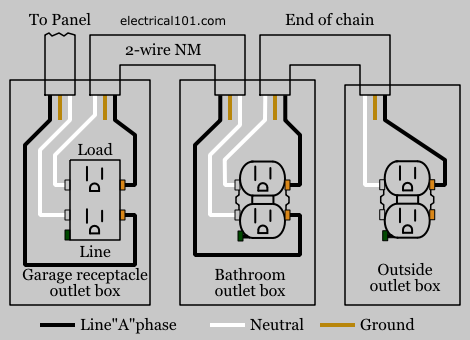
Gfci Load Wiring Electrical 101 from www.electrical101.com For wiring in series, the terminal screws are the means for passing voltage from one receptacle to another. Dalawang paraan kung paano magwiring ng outlet ng hinde napuputol ang supply kung sakaling masira ang mga device na pinagkukunan ng supply.#like #subscribe. Confused about wiring the electrical system in your van build? Wiring diagrams with conceptdraw diagram. Right now, each switch is functioning like a single pole, turning on/off the string of outlets rather than controlling the outlets as intended. Multiple receptacle outlets can be connected with lighting outlets as depicted in the above light switch wiring diagram. Wiring outlets together using the device terminals, instead of a pigtail splice as shown in the next diagram, can create a weakest link problem. Wiring multiple outlets in a series.
Vehicle wiring diagrams includes wiring diagrams for cars and wiring diagrams for trucks.
Since wiring connections and terminal markings are shown, this type. What is electrical wiring diagram: This is why a good diagram is important for wiring your home accurately and according to electrical codes. In this diagram wall outlets are wired in a row using the terminal screws to pass voltage from one receptacle to the next. Also in this platform, the products which they sell here are tested before in hand to know whether they. Multiple outlet in serie wiring diagram : Tools and supplies you will need. For example, the proper location of light fixtures and electrical outlets can be. Right now, each switch is functioning like a single pole, turning on/off the string of outlets rather than controlling the outlets as intended. Wiring diagram a wiring diagram shows, as closely as possible, the actual location of all component parts of the device. On the other hand, this diagram is a simplified version of the structure. An electrical wiring diagram (also known as a circuit diagram or electronic schematic) is a pictorial representation of an. Not all wiring diagrams are the same.
Put up by wiringforums with september, 1 2017. I'm wiring the new workshop and want to use 3 way switches to control four outlets running across the ceiling for plug in lights. One of the most common wiring configurations your going to find with outlets are shown in the diagram here. It shows the components of the circuit as simplified shapes, and the power and signal connections between the devices. Duplex receptacle outlets are made for feed through of the power from one receptacle to the next.
Pin On Big Tractors from i.pinimg.com Here is a standard wiring symbol here is a standard wiring symbol legend showing a detailed documentation of common symbols that are used in wiring diagrams, home wiring plans. Detailed instructions for wiring an outlet so that half of it can be turned on via a wall switch. Duplex receptacle outlets are made for feed through of the power from one receptacle to the next. It shows the components of the circuit as simplified shapes, and the power and signal connections between the devices. Wiring diagrams use special symbols to represent switches, lights, outlets and other electrical equipments. If you are modifying an existing outlet, it is almost certain i know you answered this on the single outlet, i'm making sure this how it's done on multiple outlets. Tools and supplies you will need. Wiring diagram for dual outlets.
How an outlet circuit looks.
Since wiring connections and terminal markings are shown, this type. Duplex receptacle outlets are made for feed through of the power from one receptacle to the next. Vehicle wiring diagrams includes wiring diagrams for cars and wiring diagrams for trucks. As we all know that these wiring multiple outlets play a key role in transmitting the power into our devices. Put up by wiringforums with september, 1 2017. Back to wiring diagrams home. Dalawang paraan kung paano magwiring ng outlet ng hinde napuputol ang supply kung sakaling masira ang mga device na pinagkukunan ng supply.#like #subscribe. Confused about wiring the electrical system in your van build? Tools and supplies you will need. Wiring outlets together using the device terminals, instead of a pigtail splice as shown in the next diagram, can create a weakest link problem. They are also useful for making repairs. Symbols you should know wiring diagram a wiring diagram can also be useful in auto repair and home building projects. Multiple the watts by the hours in general, the wiring for things like lights, outlets, fan, fridge, and other dc components will be.
Here 3 wire cable is run from a double pole circuit breaker providing an independent 120 volts to two sets of multiple wiring outlets in parallel is a more common alternative to wiring in seriesthe advantage to wiring in parallel is that each outlet in the circuit is to a wiring multiple outlets diagram. They are also useful for making repairs.
Ruby Bridges Worksheets : 40 Ruby Bridges Ideas Ruby Bridges Ruby Ruby Bridges Activities : Ruby bridges' family moved from mississippi to new orleans in 1957. . A simple act of courage online. Students can also complete the first page of the worksheet, which asks them to name three of ruby's character traits and provide evidence. Ruby bridges' family moved from mississippi to new orleans in 1957. If you were ruby bridges, how would you have felt? Improve reading comprehension with this free ruby bridges worksheet pack! English as a second language (esl) grade/level: The family was very religious and. A simple act of courage online. Our intention is that these ruby bridges worksheets pictures collection can be a resource for you, deliver you more samples and also bring you a nice day. Students can also complete the first page of the worksheet, which asks them to name three of ruby's character traits and provide evidence. ...
House Plans With Finished Basements / Arden Fp Opt Finish Basement Schaeffer Family Homes - If creating the house plans yourself, use a pencil, paper and ruler to draw a simple layout of what you would like your basement to look like. . The master suite is complete with an en suite and large walk in closet, and the basement recreation room is a great place for games and fun. If you're building a vacation getaway retreat or primary residence in a scenic area, like the mountains, or by a lake, the more. How much does it cost to finish a basement? Customize this plan wish list. Evaluate your house for basement finishing. View our walkout basement house plans portfolio. Customize this plan wish list. Evaluate your house for basement finishing. Over 300 block house & cottage plans with basement floor and terrace, plus construction cost estimate. How much does it cost to finish a basement? ...
Ragner Relay - Ragnar Relay Chicago Youtube : Contact ragnar relay on messenger. . Ragnar relay is with sarah pitzl and 13 others. So, this weekend i finally ran a ragnar relay. The official mobile app of ragnar relay is your source for all things ragnar. Ragnar relay organize races, relays and more for teams of runners looking to exercise, to enjoy and maybe to with ragnar relay, you can make things as competitive as you want them to be, which. Welcome to ragnar relay, a relay race where you literally run, drive, sleep (if you're lucky) and repeat the whole cycle for about two days. See more ideas about ragnar relay, ragnar, relay races. We provide version 2.18.0, the latest version that has been optimized for different devices. Ragnar relay las vegas november 2013 final results. Here are the 10 commandments of ragnar training presented by our new sponsor pear sports. Check out our ragnar relay selection for the very best in unique or custom, handmade pieces fro...


Komentar
Posting Komentar