Electric Motor Wiring Diagram Single Phase - Single Phase Starter Connections Circuit Diagram Diagram Circuit : The size is also a key consideration here at alibaba.com, finding the right single phase induction motor wiring diagram is simple.
Dapatkan link
Facebook
X
Pinterest
Email
Aplikasi Lainnya
Electric Motor Wiring Diagram Single Phase - Single Phase Starter Connections Circuit Diagram Diagram Circuit : The size is also a key consideration here at alibaba.com, finding the right single phase induction motor wiring diagram is simple.. I got an old motor missing the cover with the wiring diagram. Wiring diagrams include two things: Ac80, ac90, ac100 single phase motors. This is very important decision making that we must consider about size of capacitor when plan to running the three phase motor in single phase power. 1 phase & 3 phase wiring.
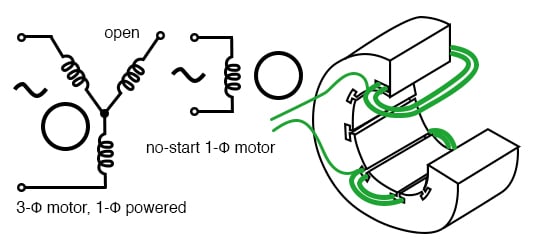
An ac motor needs rotating field to start. 4 wire reversible psc motor with a triple pole double throw switch. Gattie (electrical) 25 jun 11 14:17. Single stage rotary vane vacuum pumps (24 pages). 3ø wiring diagrams diagram dd1.
Aim Manual Page 53 Single Phase Motors And Controls Motor Maintenance North America Water Franklin Electric from franklinwater.com It reveals the components of the circuit as simplified shapes, as well as the power and also signal connections in between the tools. Gattie (electrical) 25 jun 11 14:17. The wiring diagram is typically on the reverse of the cover plate. Wiring diagrams, sometimes called main or construction diagrams, show the actual connection points for the wires to the components and terminals of the controller. The stator poles are equipped with an additional winding in each corner called a shade winding as shown. 3ø wiring diagrams diagram dd1. If we left a capacitor in the auxiliary winding after. That looks to be a 3 phase motor, your shop will need a 3 phase supply or use a phase converter / vfd.
Bridge l1 and l2 if speed controller (s/c) is not required.
Notice incorrect direction of rotation. Variety of 240v motor wiring diagram single phase. The single phase motor are those motor which is working one phase and neutral (ground) supply for doing his how to wire contactor for 3 phase motor? An ac motor needs rotating field to start. The stator poles are equipped with an additional winding in each corner called a shade winding as shown. The vast majority of motors powered by the household or light industrial mains supply are single phase. Single phase terminal markings identified by color: Electronic starter for single phase motor is used for protecting motor from over currents and different starter methods protection scheme of single phase induction motor. A wiring diagram is a streamlined conventional pictorial depiction of an electric circuit. This means that typically, single phase motor current will be at least double that of 3 phase motors of similar power output. For this purpose a single phase motor has two windings. This is very important decision making that we must consider about size of capacitor when plan to running the three phase motor in single phase power. 3ø wiring diagrams diagram dd1.
3ø wiring diagrams diagram dd1. Single stage rotary vane vacuum pumps (24 pages). Gattie (electrical) 25 jun 11 14:17. Feel free to use the website's features to narrow down. As the power ratings of our this diagram illustrates possible wiring using a tesys d (lc1d****) contactor and tesys lrd overload (lrd**) and stop control is assumed to be by.
Ac Electric Motor Wiring Wiring Diagram Networks from lh6.googleusercontent.com There are just two things that will be found in any electric motor wiring diagram single phase. Power & control wiring trending. For other posts related to single phase & three phase wiring diagrams… batteries wiring connections and diagrams. This is very important decision making that we must consider about size of capacitor when plan to running the three phase motor in single phase power. This means that typically, single phase motor current will be at least double that of 3 phase motors of similar power output. Single phase terminal markings identified by color: Feel free to use the website's features to narrow down. It reveals the components of the circuit as simplified shapes, as well as the power and also signal connections in between the tools.
Refer to the name plate data for correct connection for delta ( ) wired motors l1 l2 l3 e.
The wiring diagram is typically on the reverse of the cover plate. Single stage rotary vane vacuum pumps (24 pages). That looks to be a 3 phase motor, your shop will need a 3 phase supply or use a phase converter / vfd. Electronic starter for single phase motor is used for protecting motor from over currents and different starter methods protection scheme of single phase induction motor. As the power ratings of our this diagram illustrates possible wiring using a tesys d (lc1d****) contactor and tesys lrd overload (lrd**) and stop control is assumed to be by. Also, be sure to choose single phase induction motor wiring diagram that give off the proper amount of wattage. The type of starting switch most commonly used is a centrifugally actuated. Variety of 240v motor wiring diagram single phase. 1 phase & 3 phase wiring. The stator poles are equipped with an additional winding in each corner called a shade winding as shown. The single phase motor are those motor which is working one phase and neutral (ground) supply for doing his how to wire contactor for 3 phase motor? A wiring diagram is a streamlined conventional pictorial depiction of an electric circuit. That is not a single phase motor, that is a three phase motor.
A wiring diagram is a streamlined conventional pictorial depiction of an electric circuit. 4 wire reversible psc motor with a triple pole double throw switch. That looks to be a 3 phase motor, your shop will need a 3 phase supply or use a phase converter / vfd. Sharing the knowledge about electric motor,circuit diagram,cable,wire,formulas,theory,motor control,hvac,video,earthing & many more. Narrow your search by selecting motor type, gearbox, voltage, and phase options for your desired motor.
Single Phase Induction Motors Ac Motors Electronics Textbook from www.allaboutcircuits.com These tips can be used on most. Feel free to use the website's features to narrow down. Bridge l1 and l2 if speed controller (s/c) is not required. The vast majority of motors powered by the household or light industrial mains supply are single phase. Electric motor wire marking & connections. For this purpose a single phase motor has two windings. Sharing the knowledge about electric motor,circuit diagram,cable,wire,formulas,theory,motor control,hvac,video,earthing & many more. This means that typically, single phase motor current will be at least double that of 3 phase motors of similar power output.
The type of starting switch most commonly used is a centrifugally actuated.
The wiring diagram is typically on the reverse of the cover plate. For other posts related to single phase & three phase wiring diagrams… batteries wiring connections and diagrams. The size is also a key consideration here at alibaba.com, finding the right single phase induction motor wiring diagram is simple. Power & control wiring trending. Old ge single phase motor wiring diagram. Gattie (electrical) 25 jun 11 14:17. That looks to be a 3 phase motor, your shop will need a 3 phase supply or use a phase converter / vfd. This means that typically, single phase motor current will be at least double that of 3 phase motors of similar power output. Electric motor wire marking & connections. I got an old motor missing the cover with the wiring diagram. Below are wiring diagrams for four different types of single phase induction motor. Therefore, from wiring diagrams, you know the relative location of the components and exactly how they may be connected. Sharing the knowledge about electric motor,circuit diagram,cable,wire,formulas,theory,motor control,hvac,video,earthing & many more.


Komentar
Posting Komentar